Multi Process Robotic Cell
The Multi-Process Robot Cell (MPRC) is designed to address the increasing demand for customized manufacturing. Unlike traditional assembly lines, which require significant setup time to modify parts being processed, the MPRC offers a more flexible solution by replicating the functions of three assembly workstations, with added capabilities for pneumatic testing and packaging.
The stations are arranged in a circular configuration around a central 6-DOF (Degrees of Freedom) industrial robot. This robot is equipped with a pneumatic master end effector, while slave tools are positioned at the corners of the cell, allowing the robot to perform multiple tasks efficiently.
One of the key advantages of the MPRC is the balance between cycle time and customizability. While traditional robotic cells use a PLC to interface sensors and trigger static programs in the robot controller, the MPRC leverages Siemens KUKA libraries to directly control each movement of the robot using ladder logic in the PLC. This approach allows for the programming of multiple subroutines, enabling the cell to process a wide variety of parts without the need for extensive reconfiguration.
The MPRC exemplifies the flexibility and adaptability needed for modern manufacturing environments, offering a highly efficient, customizable solution for processing diverse parts in a streamlined setup.
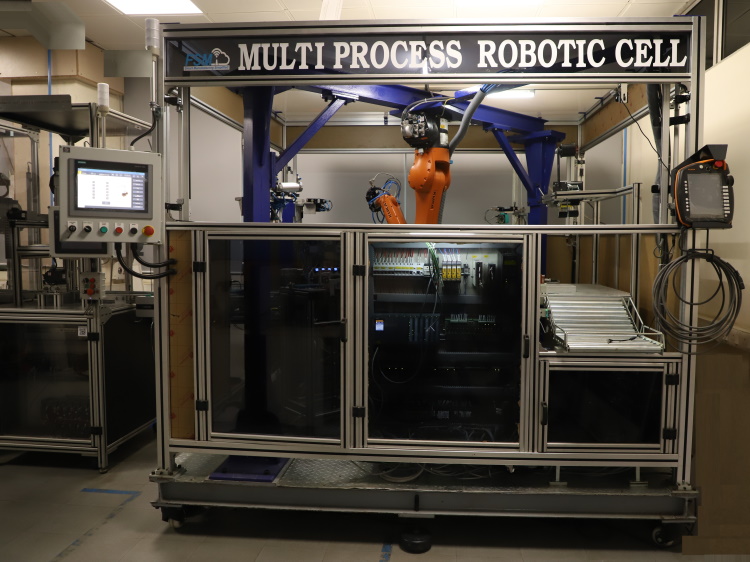

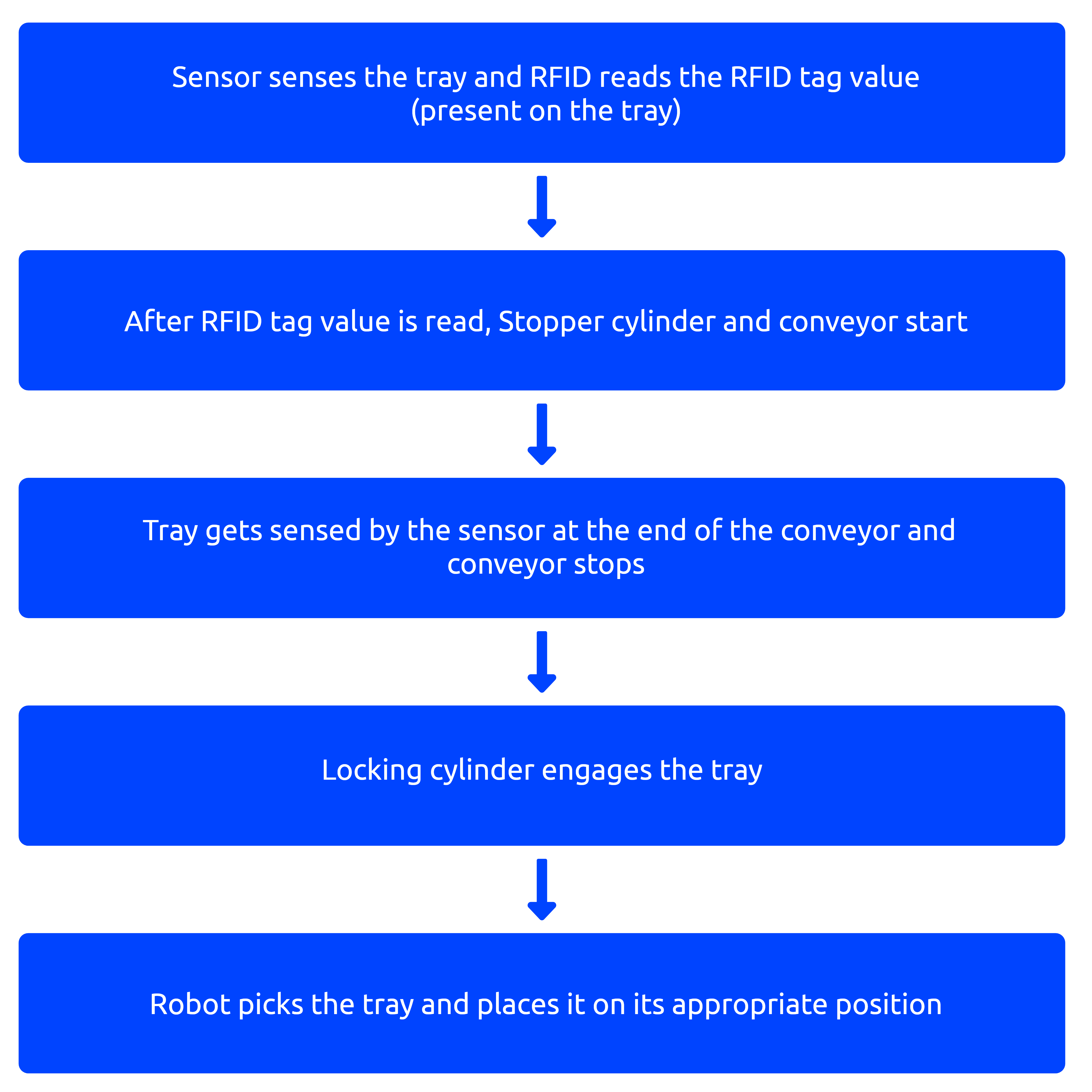
1.Conveyor station:- Use to transfer the inventory tray or pallet to the place where robot can pick them.
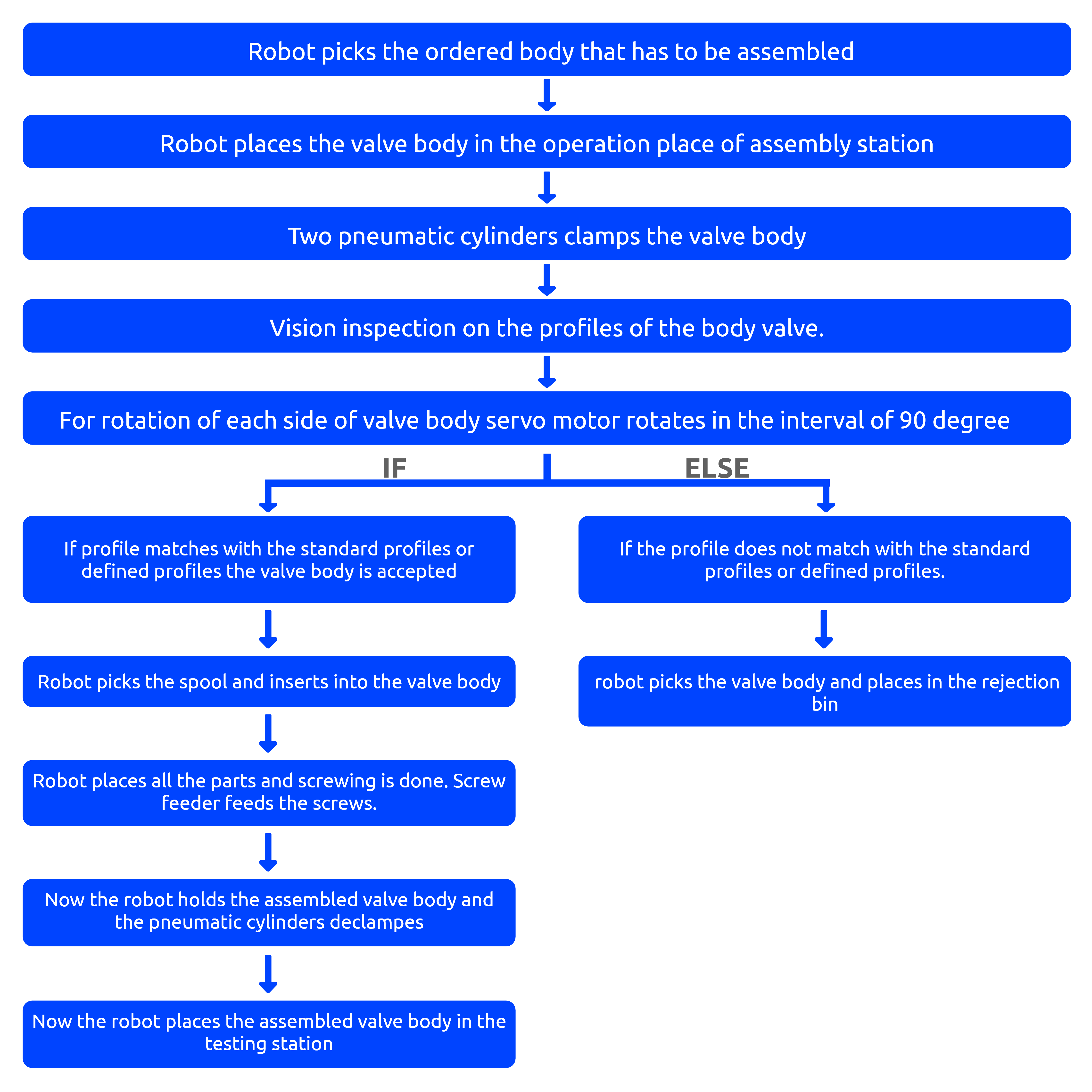
2. Assembly Station:- All the parts (Axisymmetric and prismatic parts) will be assembled and screwed on the valve body in this station. Along with that inventory scanning and vision inspection of the valve bodies will be done in this station.
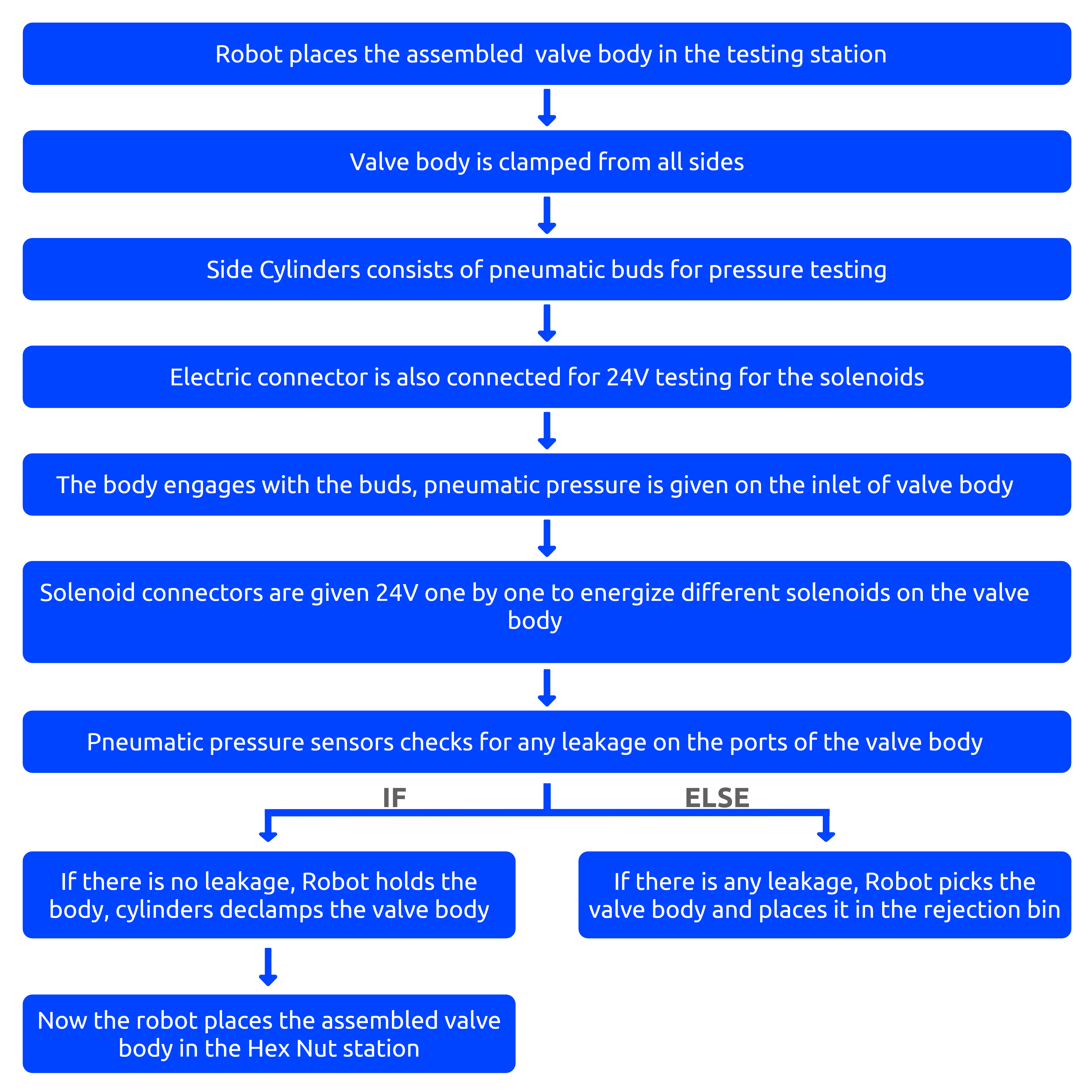
3.Testing Station:- All the ports of the valve body will be tested in this station. If there is any leakage, valve body will be rejected.
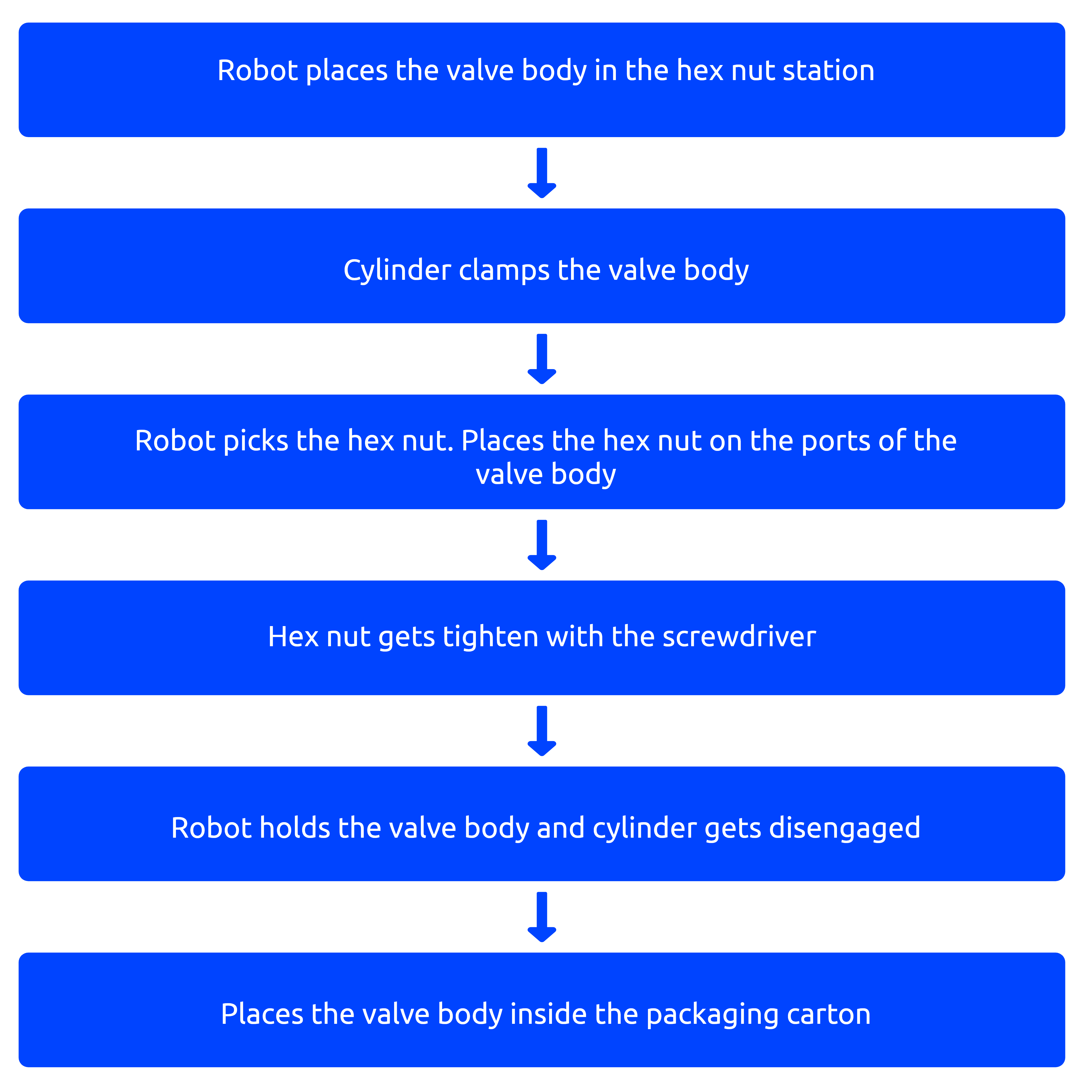
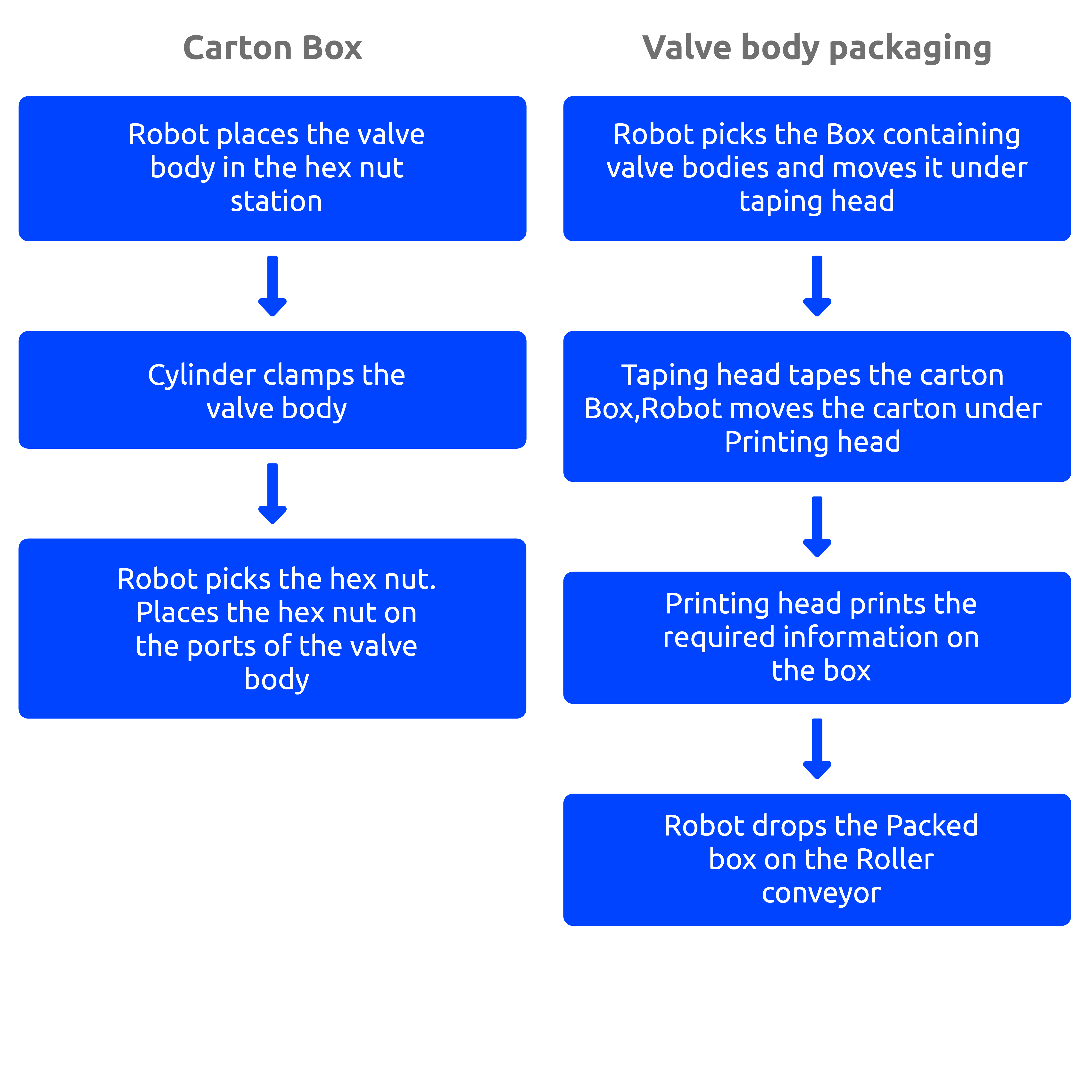
4.Hex nut assembly station:- Hex nut will be placed on the body in this station.
5. Packaging station :- Assembled valve bodies will be placed in a box and packaging is done. A printing head will print the required details( Type of bodies ,number of bodies, date of assembly etc…) on the box and then the box will be dispatched.
Hardware and Control devices
2. DI and DO: - 32-point digital input and 32 point digital output module is connected on the base rack with the plc.
3. 6 Axis Kuka robot and one axis:- 6 Axis kuka robot performs all the motion operation in the cell.7th axis rotates the valve body during assembly and inspection.
4. QR code scanner:- QR code scanner performs the inventory check as it scans the QR code present on body. After scanning a body, plc gets the data of that particular body and its location on the tray.
5. Laser based Vision sensor:- This sensor inspects all the four faces of the body and if it is OK then the station will pass the body to next station or else it will reject the body and picks another body of the same type.
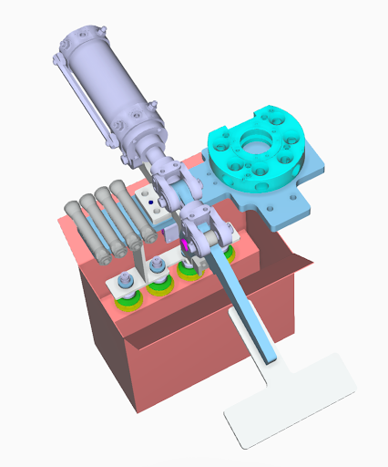
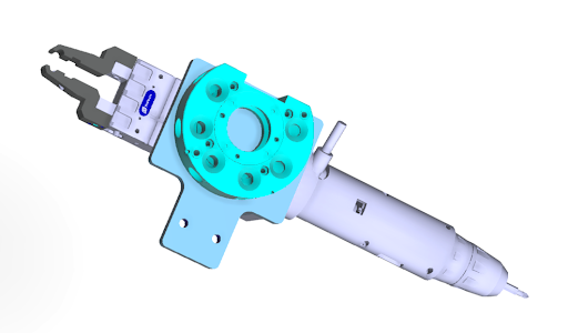
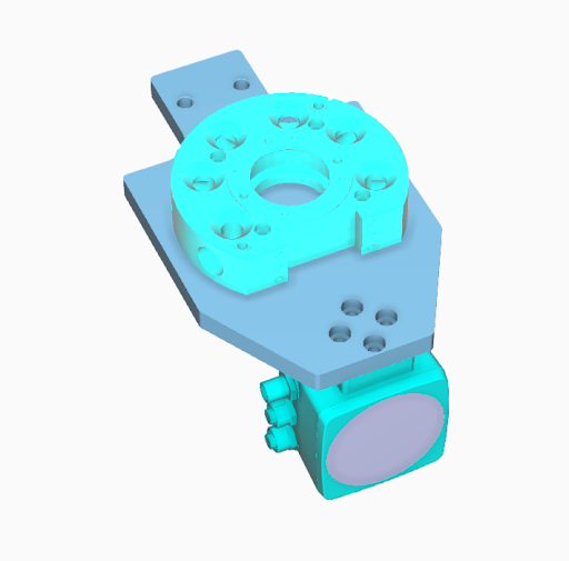
6. Tool Changers :- Different slave tool changersare used for different operations. These slave tool changers engages with the master tool changer(Present on the Robot arm) when required. Tool changers in this cell are used for:- QR code scanner,Pneumatic gripper and Screwdriver, Vacuum Gripper
Conveyor Station

Assembly Station

Testing Station

Hex Nut Station

Packaging and Printing Station

Tool Changers
